
Application · Twin screw compounding
Engineering Plastics Compounding: Glass-Filled PA, PC/ABS and PBT Lines
The highest-value single-machine application in compounding — and the easiest one to ruin. Side feeding, fibre-length protection and moisture control decide the mechanical properties long before the barrel temperature does.
Quick answer
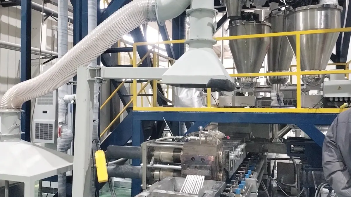
An engineering plastics compounding line is a twin screw extruder with side feeding for glass fibre, vacuum devolatilization and a wear package. The resin melts first, fibre goes in after, and everything downstream of the fibre entry is designed to protect fibre length: no 90° kneading blocks, gentle 45° elements only, bimetallic barrel liners. PA66+GF30 runs at 240–280 °C barrel with moisture below 0.1%; typical output is 60–700 kg/h for glass-filled grades and up to 1,000 kg/h for blends on a KTE-95.
Three product families, one process logic
Glass-fibre reinforcement, toughening and alloying cover most engineering plastics compounding. The machine logic is identical in all three: dry the resin, melt it clean, add the modifier downstream, vacuum out the moisture, pelletize without breaking what you built.
| System | Composition | Ratio | Critical point |
|---|---|---|---|
| PA66 + GF30 automotive, electrical |
PA66 / E-glass chopped strand 3–4.5 mm / silane coupling / amide wax lubricant / antioxidant | 68 / 30 / 0.5 / 0.5–1 / 0.2–0.5 % | PA66 dried at 120 °C × 4 h, moisture <0.1% — hydrolysis is the number-one cause of batch variation |
| Toughened PA | PA66 / POE-g-MAH / antioxidant | 70–80 / 15–25 / 0.3–0.5 % | Grafted POE reacts with PA end groups — compatibilized, not just blended |
| PC/ABS alloy | PC / ABS / MBS impact modifier / antioxidant 1076 + 168 | 60–70 / 30–40 / 3–5 / 0.2–0.4 % | Both resins dried, PC at 120 °C × 4 h |
| PP / talc bumper compound | PP copolymer / talc 1,250 mesh / POE / coupling agent | 70 / 15–20 / 5–10 / 0.5–1 % | Lower barrel window, 190–220 °C — see the temperature profile page |
Automotive grades are material-certification sensitive. A formulation is validated against the customer's target specification, not copied.
Fibre length decides everything
Chopped glass enters the extruder at 3–4.5 mm. Published fibre-length measurements on twin screw compounded pellets show it leaves at 0.2–1 mm, usually below 0.7 mm. That is not a defect of one machine — it is what high shear does to brittle fibre, and it is why fibre length, not fibre content, is the variable that separates a good compounded grade from expensive filler.
The consequence is measurable. At the same 30% glass loading in PET, long-fibre pellets beat short-fibre compounds by:
Where the line is drawn
A standard twin screw with side feeding makes short-fibre compound — 0.2–1 mm retained fibre. Long-fibre (LFT) pellets of 11–25 mm cannot be made this way: they require a continuous roving pulled through a melt-impregnation die, then cut. If an enquiry specifies LFT pellets, quote an impregnation line, not a side-feed compounding line. Quoting the wrong machine here costs the project.
Process flow for engineering plastics compounding
- Dry the resin. PA, PC and PBT at 120 °C × 4 h to below 0.1% moisture. Skipped drying shows up later as hydrolysed molecular weight and unexplained batch-to-batch scatter.
- Main feed. Resin pellets in by volumetric or gravimetric feeder at the main throat.
- Melting. Two to three barrel sections after the main feed, with staggered 45° kneading blocks, complete the melt.
- Glass side feeding — critical point one. Fibre enters only after the melt is fully formed, through side feeders. For GF30, distribute the addition over 2–3 side ports: add at one port, disperse, add at the next.
- Fibre protection — critical point two. Downstream of every glass entry: large-pitch conveying elements and moderate shear — tooth-type elements beat kneading blocks. No 90° kneading blocks after glass, ever. Fibre length survives, and with it impact strength.
- Vacuum devolatilization. Standard at L/D 40–44, one vent section, pulling moisture and volatiles from PA and PC.
- Filtration. 40–80 mesh. Finer screens on glass-filled melts clog fast and break fibre at the breaker plate.
- Pelletizing. Water-cooled strand for PA, PC and PBT; underwater hot-face on high-output lines.
- Wear management. Glass fibre is a continuous abrasive on flight tips and bores. D-series high-torque drives with bimetallic liners are the standard answer, not an upgrade option.
| System | Barrel, °C | Note |
|---|---|---|
| PA66 + glass fibre | 240–280 | Die set slightly below the maximum melt temperature |
| PC / PC-ABS | 230–260 | Both resins dried before the hopper |
| PBT / PET modification | 240–260 | PET needs drying plus vacuum at the vent |
| PP / talc | 190–220 | Wide flat plateau, see the profile-by-material page |
Equipment configuration
| Section | Recommendation | Why |
|---|---|---|
| Main extruder | KTE-50 to KTE-95, D series for high glass loading and high output | D-series gearboxes carry roughly 1.7–2× the torque of the same-size B series at equal diameter |
| L/D ratio | 40–44 | Long enough for melt, side feed, dispersion and vacuum; short enough to limit fibre attrition and PA residence time |
| Feeding | Gravimetric main feed + 2–3 twin-screw side feeders | Splitting the glass addition over several ports disperses each dose before the next arrives |
| Screw elements after glass | Large-pitch conveying + tooth-type mixing, 45° kneading only | 90° blocks after the glass entry shred fibre and tank impact strength |
| Barrel and screw material | Bimetallic liners, W6Mo5Cr4V2 elements | Glass is abrasive; liners turn a screw replacement into a liner replacement |
| Vacuum | One vent section, standard | Removes moisture and volatiles; PA and PC both demand it |
| Pelletizing | Water-cooled strand (PA/PC/PBT) or underwater hot face at high output | Sample catalogue recommendation for all three resin families |
Output by model
| Process | KTE-50 | KTE-65 | KTE-75 | KTE-95 |
|---|---|---|---|---|
| Engineering resin blends PP+PE, PBT+PET, PA/PC/TPU+ABS | 80–180 | 160–250 | 300–400 | 600–1,000 |
| Glass / carbon fibre reinforced PE, ABS, PBT, PET, PA, PC, PPS | 60–140 | 140–200 | 220–300 | 500–700 |
| Long / short glass fibre same resins + PPO | 80–140 | 180–260 | 280–360 | 550–750 |
Fibre-reinforced grades run below blend outputs at equal machine size: dispersion and fibre protection cost throughput. Quote from the lower third of the range and confirm with a material trial.
Three mistakes that cost the most
1. Putting glass fibre in the main feed
The main feed section carries the highest shear in the machine, and it grinds fibre into powder while accelerating wear on exactly the elements that cannot be protected. Fibre goes in at a side port after the melt — always. The wear argument is secondary but real: main-fed glass multiplies abrasion in the melting zone.
2. A 90° kneading block downstream of the glass entry
One 90° block after the fibre port can undo an otherwise correct screw design. Dispersion after glass is the job of large-pitch conveying and tooth-type elements at 45°. The symptom of getting this wrong is a compound that hits its tensile specification but fails impact — the fibre is there, just too short to carry load.
3. Quoting a side-feed line for an LFT enquiry
Long-fibre pellets of 11–25 mm come from roving pulled through a melt-impregnation die, not from chopped strand in a side feeder. A customer who needs LFT and receives a standard compounding line has bought the wrong machine. The test question is simple: what retained fibre length does the target specification require?
FAQ
Can a twin screw extruder compound 50% glass fibre?
Mechanically yes — multiple side feeders with staged dispersion handle 50% loading. The practical limits are retained fibre length and the melt flow the target grade demands, so the starting question is the specification, not the machine. High glass content and high output both point to a D-series high-torque drive with bimetallic liners.
Why does our glass-filled PA pass tensile but fail impact strength?
Almost always fibre length. Chopped strand enters at 3–4.5 mm and leaves a twin screw at 0.2–1 mm; aggressive kneading after the glass entry shortens it further. Fibre below critical length pulls out instead of carrying load — the compound gains stiffness but loses impact. Fix the screw configuration downstream of the fibre ports before touching the formulation.
What barrel temperature should glass-filled PA66 run at?
240–280 °C across the barrel, with the die set slightly below the maximum melt temperature. Moisture control matters more than the setpoint: PA66 dried at 120 °C × 4 h to below 0.1% moisture, or hydrolysis cuts molecular weight no matter what the controller says.
Strand pelletizing or underwater pelletizing for PA and PC?
Water-cooled strand pelletizing is the standard recommendation for PA, PC and PBT — simple, economical and gentle on modest outputs. Underwater hot-face pelletizing suits high-output lines and delivers spherical pellets, at higher cost and operating complexity.
How fast do screws wear with glass fibre?
There is no fixed interval — it depends on loading, throughput and screw speed. What is fixed is the mitigation: bimetallic barrel liners and high-speed-steel elements. Liners convert an expensive screw-and-barrel replacement into a liner swap, and they are standard specification on our glass-fibre lines rather than an option.
Can we make LFT pellets on a twin screw extruder?
Not by side feeding. Long-fibre thermoplastic pellets of 11–25 mm are made by pulling continuous roving through a special impregnation die where molten resin wets the bundle, then cutting to length. In-line D-LFT setups combine compounding and forming on one line. A standard side-feed compounding line makes short-fibre pellets, and the two products compete in different applications.
Where these numbers come from
Formulation ratios, temperature windows, output figures and process sequence are catalogue and application-engineering reference values, cross-checked against published fibre-length measurements for twin screw compounded glass fibre. They are starting points with stated conditions attached: every formulation is validated against the customer's target grade, and every output figure is confirmed with a material trial before contract commitment.
A 3–7 day trial on our barrels returns a setpoint ladder, pellet samples and a fibre-length report — before you commit to a machine.
Reference: Wikipedia: Polyamide