
Application · Masterbatch compounding
Filler Masterbatch Line: 85–90% CaCO₃ at 350–550 kg/h
Filler masterbatch is a cost-reduction product sold by the tonne, so the machine is judged on two numbers only: how much powder it can swallow, and whether the pellets still feed cleanly in the customer's film or tape line. Both are decided before the extruder.
Quick answer
A filler masterbatch line is a high-speed mixer plus a twin screw extruder with gravimetric feeding, a wear package and hot-face pelletizing. CaCO₃ of 800–1,250 mesh is surface-activated with 0.8–1.5% aluminate coupling agent at 110–120 °C for 10–15 minutes, then compounded at L/D 40–48 and 160–190 °C (PE) or 180–210 °C (PP). Up to 85% loading runs on a single KTE-65/75; 85–90% requires a two-stage line, because pressure build-up and mixing on one shaft cost too much output. Above 50% filler, strand pelletizing stops working — specify water-ring or air-cooled hot-face.
The ceiling is set by loading, not by machine size
Enquiries almost always start with "how many kilos per hour". For filler masterbatch that is the second question. The first is the filler percentage, because it decides the machine architecture, the pelletizing system and the wear specification at the same time.
| Loading | Line type | Pelletizing | What actually changes |
|---|---|---|---|
| 50–70% | KTE-50 / 65 single screw stage | Water-cooled strand | Lowest capital cost. The strand still has enough polymer to cool without snapping. |
| 70–82% | KTE-65 / 75, bimetallic liners | Water-ring hot face | Strand embrittles; die-face cutting removes the strand handling problem entirely. |
| 82–85% | KTE-75, L/D 44–48 | Water-ring or air-cooled hot face | Torque margin gets thin. Screw design shifts to conveying-dominant with 45° kneading only. |
| 85–90% | Two-stage KTE/SE-65/150 or 75/180 | Air-cooled hot face | Melting and pressure build-up are split across two machines. Output stops collapsing. |
Filler content is stated on the masterbatch, not on the customer's finished part. An 80% masterbatch let down at 30% gives 24% filler in the end product.
Process flow, step by step
- Powder activation — the step that decides everything. CaCO₃ into a high-speed mixer, heated to 110–120 °C. Coupling agent is added in one or two portions, not all at once, and the batch is activated for 10–15 minutes. Discharge hot.
- Main feed. Gravimetric loss-in-weight feeder at the main throat. Powder this fine bridges easily — the hopper needs agitation and a steep wall angle, and throughput is limited by how fast the screw flights can swallow powder, not by the drive.
- Melting and dispersion. Medium-high shear: 45° staggered kneading blocks as the backbone. Avoid an all-90° positive configuration — at high filler it generates heat and wear without improving dispersion.
- Vacuum devolatilization. One vent section pulls moisture and volatiles. Cheap insurance against porosity in the pellet.
- Filtration. Hydraulic screen changer, 60–100 mesh. Finer screens raise melt pressure and clog quickly on a filled melt.
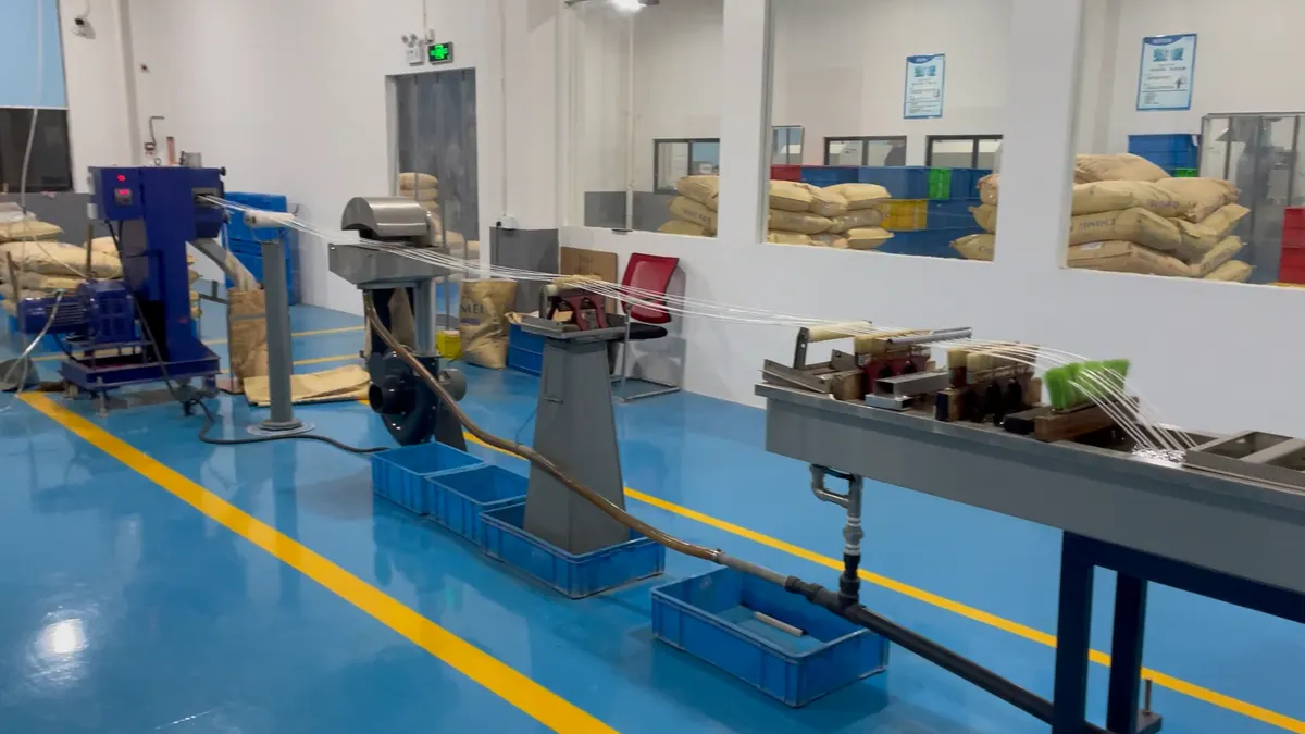
- Pelletizing. Chosen by loading, see Table 1 — strand below 50%, water-ring 30–82%, air-cooled hot face at the top end.
- Cooling, screening, silo. Vibration screen and a 1 m³ silo are the usual minimum; a second silo for grade changes is worth adding on a line that runs more than one filler.
Why 85% is a machine decision, not a screw decision
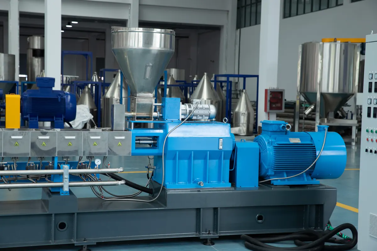
At 85% filler the melt viscosity is high enough that building pressure for the die consumes most of the available shaft torque. On a single twin screw, mixing and pressure build-up compete for the same shaft, so output falls steeply as loading climbs. A two-stage line separates the two jobs — the first stage melts and disperses, the second builds pressure — which is why the catalogue lists 85–90% under two-stage rather than under "optional upgrade".
Reference formulations
| Component | CaCO₃ masterbatch | Talc masterbatch | Function |
|---|---|---|---|
| Filler | 70–80% | 60–80% | CaCO₃ 800–1,250 mesh; talc 1,250 mesh and finer. Talc is platy, so it raises viscosity at equal loading. |
| Carrier resin | 15–25% | 20–35% | PP powder or LLDPE for CaCO₃; PP copolymer for talc. Carrier MFI should sit close to the customer's process. |
| Coupling agent | 0.8–1.5% | 0.5–1.5% | Aluminate ester for CaCO₃; titanate or silane for talc. Dose is on filler weight, not batch weight. |
| Dispersion lubricant | 3–5% PE wax + 0.5–1% stearic acid | 1–2% EBS + 3% PE wax | Lowers melt viscosity so the filler can be wetted before the die. |
| Antioxidant | 0.1–0.3% | 0.1–0.3% | Protects the carrier during repeated heating. |
Figures are percentages of the finished masterbatch. On a per-hundred-resin basis the filler runs at 300–900 phr, which is why feeding accuracy matters more here than in colour work.
Activation is the lowest-cost step and the most expensive to skip
Coupling agent is roughly 1% of the formulation and it decides whether 80% loading is achievable at all. Untreated CaCO₃ is hydrophilic: the particles agglomerate, the resin cannot wet the agglomerate interior, and the result is a pellet with dispersion defects that no screw design can fix. The customer sees it later as broken filament in a tape line or a chalky surface on a moulded part.
Three parameters carry the result: temperature 110–120 °C (below 100 °C the coupling agent does not bond, above 130 °C it starts to decompose), dosing in one or two portions so the agent meets fresh surface rather than already-coated surface, and 10–15 minutes of mixing at that temperature. The grade of coupling agent matters less than hitting those three numbers consistently. Discharge while hot — a cold batch cannot be re-activated by reheating it in the extruder.
| Carrier | Barrel, °C | Note |
|---|---|---|
| PE based | 160–190 | Flat profile works; the die runs at the low end of the window |
| PP based | 180–210 | Watch melt pressure rather than temperature at the top of the range |
| EVA / PS based | 150–190 | EVA needs the lower half to avoid acetic acid release |
Reference values only. On a 85% CaCO₃ line the barrel setpoints often look surprisingly low — the melt temperature at the die is what the customer's downstream process actually feels.
Pelletizing changes twice on the way up
| System | Throughput, kg/h | Fits when | Trade-off |
|---|---|---|---|
| Water-cooled strand | 5–2,000 | Loading below 50% | Lowest capital cost; strand snaps above 50% filler |
| Water-ring hot face | 50–1,500 | 30–82% loading | Short water contact, low drying load; needs a tight die-face setup |
| Air-cooled hot face | 50–1,800 | High fill, regular pellet shape | No water at all; larger footprint and more sensitive to ambient humidity |
Quotation point: the pelletizer is often the second-largest line item after the extruder. A customer who plans to move from 60% to 85% loading should buy the hot-face system now rather than replace a strand line in year two.
Equipment configuration
| Section | Specification | Why it matters here |
|---|---|---|
| High-speed mixer | 300 L / 55 kW for lines up to 500 kg/h; 1,000 L / 132 kW above | Activation is a batch step; mixer size sets how many batches per shift the extruder can be fed from |
| Main extruder | KTE-50 / 65 / 75 for ≤85% loading; KTE/SE two-stage for 85–90% | Torque per unit volume, not diameter, is the limiting factor at high fill |
| L/D ratio | 40–44 standard, 44–48 for HDPE high fill | Needs enough length for melt, dispersion, vent and filter; longer adds residence time without adding dispersion |
| Screw elements | W6Mo5Cr4V2, 45° staggered kneading, no all-90° section | Filler is abrasive; a 90° block at high fill wears fast and heats the melt for no dispersion gain |
| Barrel liner | Bimetallic from the start on filler lines | CaCO₃ and talc are both abrasive — liners turn a barrel replacement into a liner swap |
| Feeding | Gravimetric main feed with agitation; side feeder for talc | Platy talc bridges more than CaCO₃; splitting the addition at a side port disperses better |
| Filtration | Hydraulic screen changer, 60–100 mesh | Screen change under pressure without stopping the line |
| Vacuum | One vent section, standard | Removes moisture carried in by the powder and the carrier |
Output by model on a filler masterbatch line
| Process | KTE-50 | KTE-65 | KTE-75 | KTE-95 |
|---|---|---|---|---|
| Filler masterbatch PE / PP / PS / EVA + CaCO₃, talc, TiO₂ | 100–200 | 200–400 | 350–550 | 700–1,000 |
| High-density filler PP / PA6 / PA66 / ABS + iron, magnet or ceramic powder | 120–250 | 250–400 | 400–600 | 900–1,200 KTE-95D, bimetallic mandatory |
| Two-stage, high fill PE + 85–90% CaCO₃ | 150–300 SE-50/100 | 250–400 SE-65/150 | 400–800 SE-75/180 | 700–1,500 SE-95/200 |
Quote from the lower third of the range and confirm on trial. Metal and magnet powders are markedly more abrasive than CaCO₃ — the liner specification is not negotiable on those lines.
Talc is not CaCO₃ with a different label
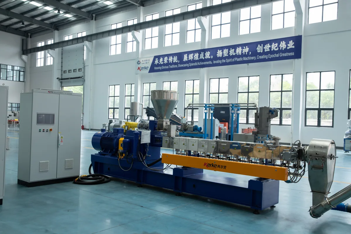
Talc differs in three ways that change the machine, and each one shows up in the quotation. It is platy, so it wets slowly and raises melt viscosity at equal loading — the practical ceiling sits a step below CaCO₃. It is more abrasive, so bimetallic liners belong in the base specification rather than the options list. It bridges in the hopper, so a talc line usually adds a dedicated silo and a side feeder to split the addition.
What the customer buys is stiffness. Published comparisons put PP compounded with talc at roughly 4,500 MPa flexural modulus against 3,200 MPa for PP with CaCO₃ at comparable loading — talc platelets act as nucleating sites, so the same filler percentage produces a stiffer, less ductile part. That is the argument for a talc line when the end product is a bumper, a crate or an appliance panel rather than a film.
State the loading basis, always
Talc masterbatch is quoted on two different bases and they are not interchangeable. In-masterbatch concentration runs up to 78–80% talc on a well-activated line. The "60–70%" figure that circulates in customer conversations refers to talc content in the customer's finished compound. Mixing the two produces a machine that is either oversized or unable to reach the promised loading. Ask which number the enquiry means before sizing anything.
Three mistakes that cost the most
1. Selling a single twin screw for 88% loading
It will run — badly. Output drops sharply as loading climbs, pellet quality degrades, and the customer blames the screw design. The honest answer at 85–90% is a two-stage line, and the conversation is easier before the purchase order than after it.
2. Quoting a strand line for a high-fill project
Above 50% filler the strand has too little polymer to stay intact between the die and the cutter. It snaps, operators slow the line down to cope, and the machine never reaches its rated output. A water-ring or air-cooled hot-face pelletizer is the fix, and retrofitting one costs more than specifying it up front.
3. Treating activation as the customer's problem
A line sold without a mixer, or with a mixer too small for the extruder, pushes activation into the extruder where it cannot be done properly. The symptom is a masterbatch that tests correctly on filler content but fails on dispersion — and dispersion is what the customer's film line actually notices.
FAQ
What is the maximum CaCO₃ loading in filler masterbatch?
85–90% with a two-stage line and surface-treated filler. Above 90% the melt becomes too viscous to pelletize reliably and output falls away. On a single twin screw, plan for 85% as the practical ceiling and expect the output to drop as you approach it.
Can one twin screw extruder reach 85% loading?
It can be pushed there, but the economics turn against it: mixing and pressure build-up compete for the same shaft, so throughput falls and pellet quality becomes inconsistent. The catalogue lists 85–90% under two-stage models for that reason, not because a single screw is mechanically incapable.
Why do our strands break at 60% filler?
Not enough polymer to hold the strand together through the water bath. Below 50% loading a water-cooled strand is the lowest-cost option; above it, move to water-ring hot-face cutting, and to air-cooled hot-face above roughly 82%. Check the die hole count and the water temperature as well — an over-long bath makes a marginal strand worse.
How fine should the CaCO₃ be?
800–1,250 mesh covers most masterbatch work. Coarser filler costs less but drops impact strength and gives a rougher surface; 1,250 mesh and finer is used for film, tape and thin-wall moulding. Fineness and loading trade against each other — very fine filler at very high loading is where dispersion problems appear.
Do filler masterbatch lines really need bimetallic barrels?
Yes on any line that runs continuously. CaCO₃ and talc are both abrasive, and wear shows up first at the flight tips and in the metering zone. Bimetallic liners convert a screw-and-barrel replacement into a liner swap; on a line running 24 hours a day the difference pays for itself well inside the first liner interval.
Which L/D ratio for filler masterbatch?
40–44 is the standard window; 44–48 is used for HDPE high-fill and for lines that need both a vent and a filter. Among published filler masterbatch process disclosures, 44:1 is by far the most common single value. Extra length beyond that adds residence time without adding dispersion.
What does a filler masterbatch line cost?
It depends on four variables: target output, maximum loading, pelletizing system and wear specification. Two lines rated at the same tonnage can differ substantially once a two-stage configuration and a hot-face pelletizer are included. Send the loading and the hourly output and the quotation can be built around those two numbers rather than a generic range.
Where these numbers come from
Loading ceilings, activation parameters, screw configuration rules and output tables are drawn from our own catalogue data and application engineering records, cross-checked against published filler masterbatch process disclosures covering 44:1 and 40:1 screw geometries. Every figure is a reference value with its condition attached: formulations are validated against the customer's filler and carrier, and output is confirmed by a material trial before contract commitment.
A 3–7 day trial returns a setpoint ladder, pellet samples and a dispersion check — enough to quote the line on measured output instead of a catalogue range.
Reference: Wikipedia: Masterbatch