
Application · Engineering Plastics
Engineering Plastic Compounding: PA, PC, PBT, ABS & Alloys
Engineering plastics punish shortcuts in two places: drying (PA and PC want 120 °C for four hours, not 80 °C overnight) and fibre handling (side feed position decides how much of the fibre survives). A reference engineering plastic compounding page from Kerke.
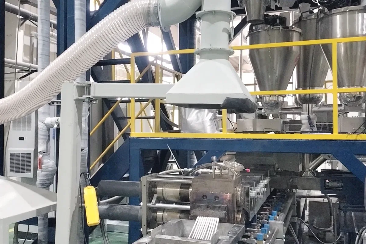 Engineering Plastic Compounding — workshop photo 1, Kerke workshop, Nanjing
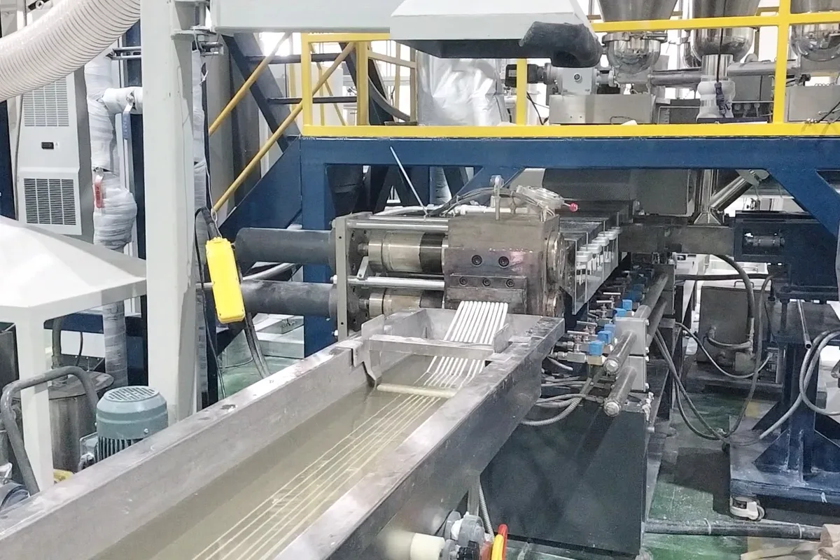 Engineering Plastic Compounding — workshop photo 2, Kerke workshop, Nanjing
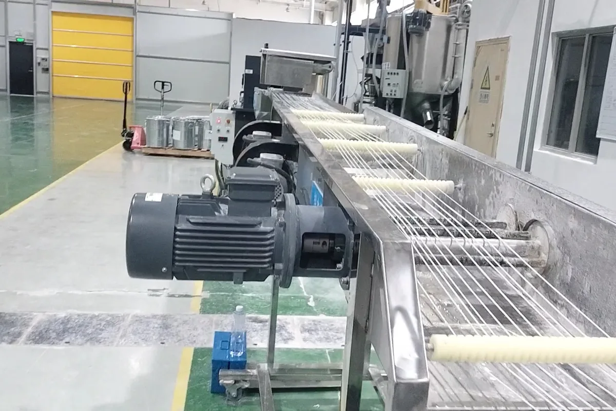 Engineering Plastic Compounding — workshop photo 3, Kerke workshop, Nanjing
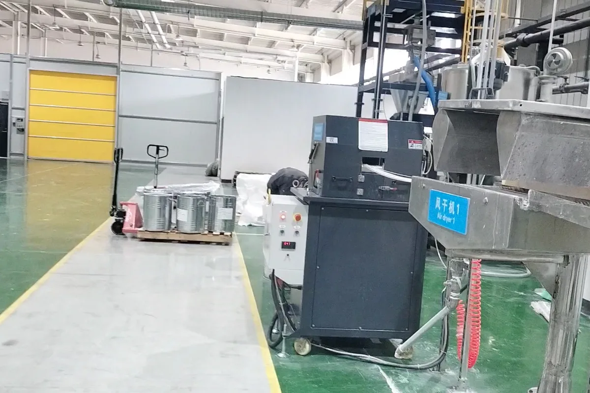 Engineering Plastic Compounding — workshop photo 4, Kerke workshop, Nanjing
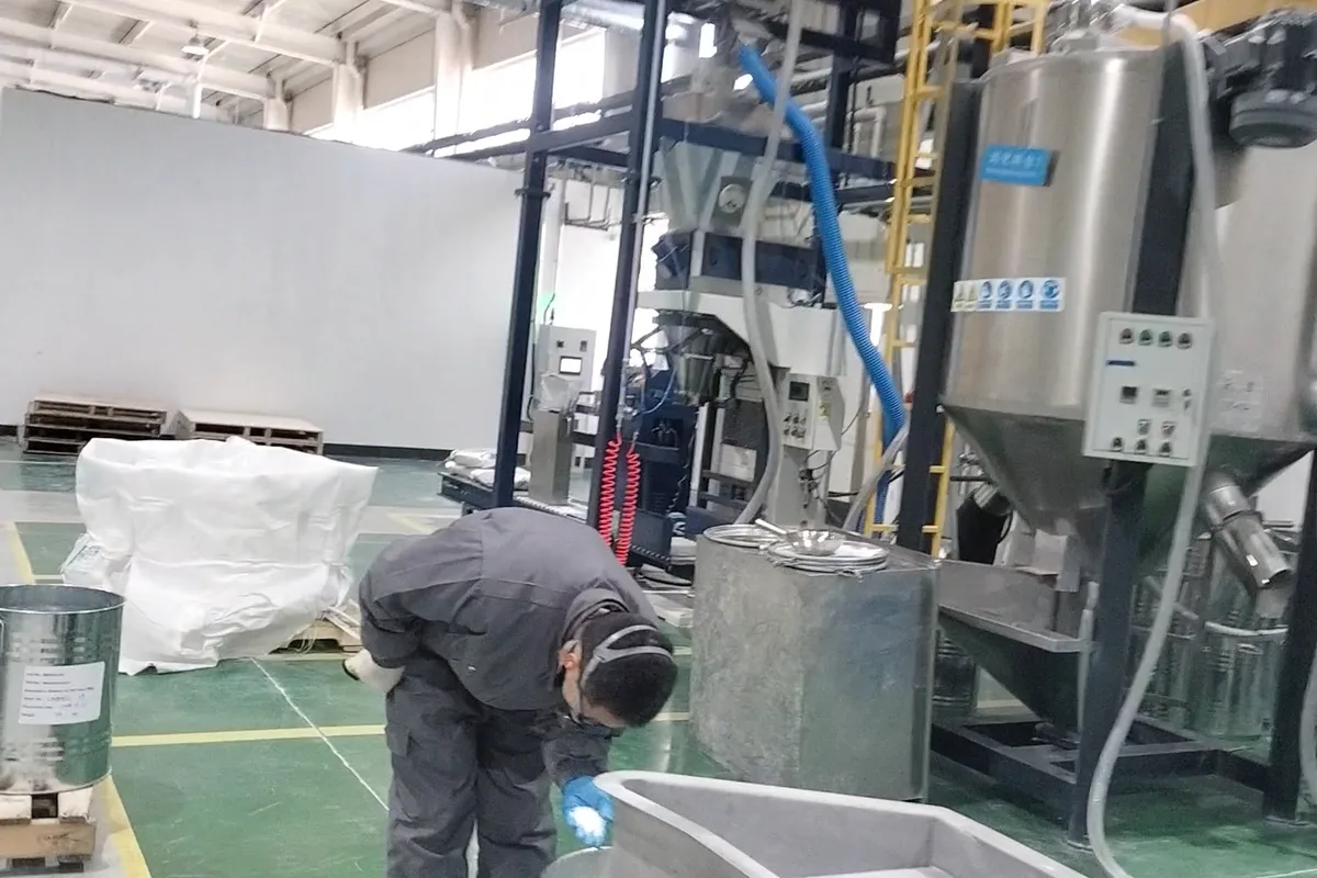 Engineering Plastic Compounding — workshop photo 5, Kerke workshop, Nanjing
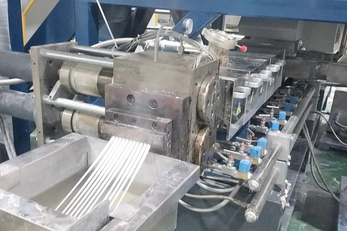 Engineering Plastic Compounding — workshop photo 6, Kerke workshop, Nanjing
Quick answer
Engineering plastics compounding (PA, PBT, PC, ABS, PC/ABS, POM) runs on high-torque twin screws with L/D 40–48, downstream fibre or filler feeding, vacuum devolatilization and 300–3,000 kg/h output. Torque density (T/A³ 8–12) matters more than motor power for these formulations.
Workshop photos and a running video — shot on our own lines, not stock images.
What sets the limit
Resins are dried, metered and melted; glass fibre or mineral filler is added at barrel 4–6; the melt is devolatilized under vacuum, filtered and pelletized underwater or by strand.
| Parameter | Value / range |
|---|---|
| Polymers | PA6/PA66, PBT, PC, ABS, PC/ABS, POM |
| L/D | 40–48 |
| Torque class | D-type gearbox, T/A³ 8–12 |
| Downstream | Side feeder, 2-stage vacuum, screen changer |
| Output (reference) | 300–3,000 kg/h |
| Model | KTE-65D, KTE-75D, KTE-95D |
Output figures are measured on the reference material stated above. Filler grade, bulk density and moisture move output by ±15% — that is why every quotation we issue is tied to a trial report.
Process flow, step by step
- FeedingLoss-in-weight dosing of polymer and filler; side feeder or liquid injection where the formulation needs it.
- Melting and dispersingScrew geometry with 45°/90° kneading blocks; barrel profile set by the polymer.
- DevolatilizationVacuum vent at −0.06 to −0.09 MPa removes moisture and volatiles before the die.
- Pressure build-upThrottle or discharge section stabilises die pressure; a melt pump where gauge control matters.
- Pelletizing and packingdie-face or strand pelletizing, see the pelletizing page; then centrifugal dryer, vibrating screen and bagging.
Equipment configuration
| Stage | Equipment | Why this choice |
|---|---|---|
| Main machine | Co-Rotating Twin Screw Extruder | Architecture follows the filling level and the mixing duty, not the required tonnage. |
| Screw geometry | Building-block elements, W6Mo5Cr4V2, bimetallic liner | Wear package for abrasive filler; mixing blocks only where dispersion demands them. |
| Feeding | Loss-in-weight feeder, side feeder where needed | Recipe accuracy: ±0.5% short term on the weighed component. |
| Pelletizing | Pelletizing system | Chosen by polymer and filler ceiling — water contact is the deciding column. |
| Downstream | Centrifugal dryer, vibrating screen, bagging | Fines below 2% and moisture below the specification of your downstream process. |
Output by model
| Model | Dia. (mm) | Speed (rpm) | Motor (kW) | Torque (N·m) | Output (kg/h) |
|---|---|---|---|---|---|
| KTE-50B | 50.5 | 500–600 | 55–75 | 2×525 | 80–200 |
| KTE-50D | 50.5 | 300–800 | 75–90 | 2×860 | 100–300 |
| KTE-52B | 51.4 | 500–600 | 55–75 | 2×720 | 80–200 |
| KTE-52D | 51.4 | 500–600 | 75–110 | 2×1050 | 100–400 |
| KTE-65B | 62.4 | 500–600 | 90–110 | 2×860 | 200–450 |
| KTE-65D | 62.4 | 300–800 | 132–160 | 2×1530 | 350–600 |
| KTE-75B | 71 | 500–600 | 132–160 | 2×1530 | 300–800 |
| KTE-75D | 71 | 300–800 | 200–315 | 2×2100 | 500–1000 |
| KTE-85B | 85 | 500–600 | 220–315 | 2×2100 | 550–1000 |
| KTE-95B | 93 | 500–600 | 250–315 | 2×3000 | 800–1500 |
| KTE-95D | 93 | 500–800 | 315–500 | 2×4800 | 1000–2000 |
| KTE-135B | 135 | 500–600 | 315–500 | 2×4800 | 1500–3000 |
| KTE-135D | 135 | 500–800 | 500–1000 | 2×7800 | 1500–4000 |
Three mistakes that cost the most
1. Wet PA6
Wet PA6 — moisture above 0.1% hydrolyses the polymer and impact strength collapses.
2. High shear after fibre addition breaks the fibre; fibre length below 0.3 mm gives no reinf
High shear after fibre addition breaks the fibre; fibre length below 0.3 mm gives no reinforcement.
3. Copying a PE barrel profile onto PA or PC
Copying a PE barrel profile onto PA or PC — PA wants 240–270 °C, PC 260–290 °C plus a 4 h dry at 120 °C; a generic profile silently costs IV and impact strength.
FAQ
B or D gearbox for PA+30% GF?
D-type. B-type works at reduced output and shorter screw life; the price difference is smaller than the productivity loss.
What L/D for PC/ABS?
40–44 is typical; 48 if you need two vacuum stages for low VOC grades.
What output can you guarantee for this application?
The reference band is 300–3,000 kg/h, measured on the stated material. We quote a guaranteed figure only after a trial on your own material, because filler grade, bulk density and moisture move output by ±15%.
Can we run our material before ordering?
Yes — send 25–50 kg. We return pellets, a running video and a report with temperatures, screw speed, feeder settings and output per hour. The trial is free; you cover the freight.
What is the delivery time?
30–45 working days for standard configurations, 45–70 for custom screw geometry and ODM work. Voltage and frequency are built for the destination country.
Where these numbers come from
Parameters are taken from the Kerke product parameter table and the product master data sheet, and cross-checked against commissioning records for lines in the same application. Formulations and temperature windows are typical industry values, not a recommendation for your specific compound — every figure marked reference must be confirmed on a material trial before it becomes a contractual number.
Reviewed by the Kerke process team, Nanjing. Page updated 6 November 2026.
Send 25–50 kg and we run it on our lab extruder: pellets, running video and a capacity report back in 3–7 days.
Engineering plastic compounding — the short version
Note on engineering plastic compounding: the numbers above are reference ranges from Kerke's own trial runs, not catalogue promises. Screw geometry, wear package and pelletizing method are set on the trial bench first, so the output you compare is the output you get. If your grade is not in the tables, send it — the closest configuration is usually a change of screw set, not a different machine.
Related on this site: Machine range: KTE-50B to 135D · Pelletizing methods compared · quotation and free trial · Wikipedia: Masterbatch